This guide provides the steps that we take to make the best boards possible. It's recommended that you read through everything before doing anything. Depending on your DIY kit, some of these sections may be superfluous.
Don't hesitate to reach out if any questions arise.
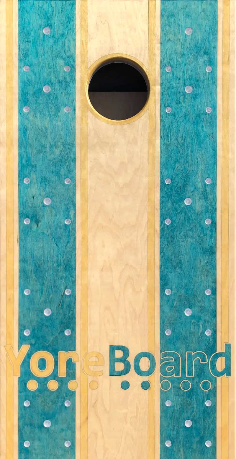
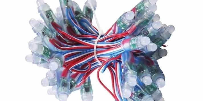
The system employs two sets of addressable light emitting diode (LED) strands per board. Each LED strand is associated with each teams' score and is composed of 26 LEDs.
There are two different main approaches that you can use. You can opt for a 7-Segment display for a “Basketball Style” scoring display or you can go with “Tally” scoring where 21 of the LEDs are used for representing the score from 0-21 and the remaining five LEDs are used for illumination, ambiance effects and indicating which team scored most recently. These ambiance LEDs are evenly dispersed between every 5 scoring LEDs within the strands.
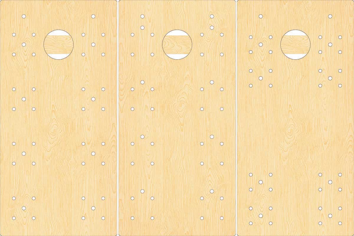
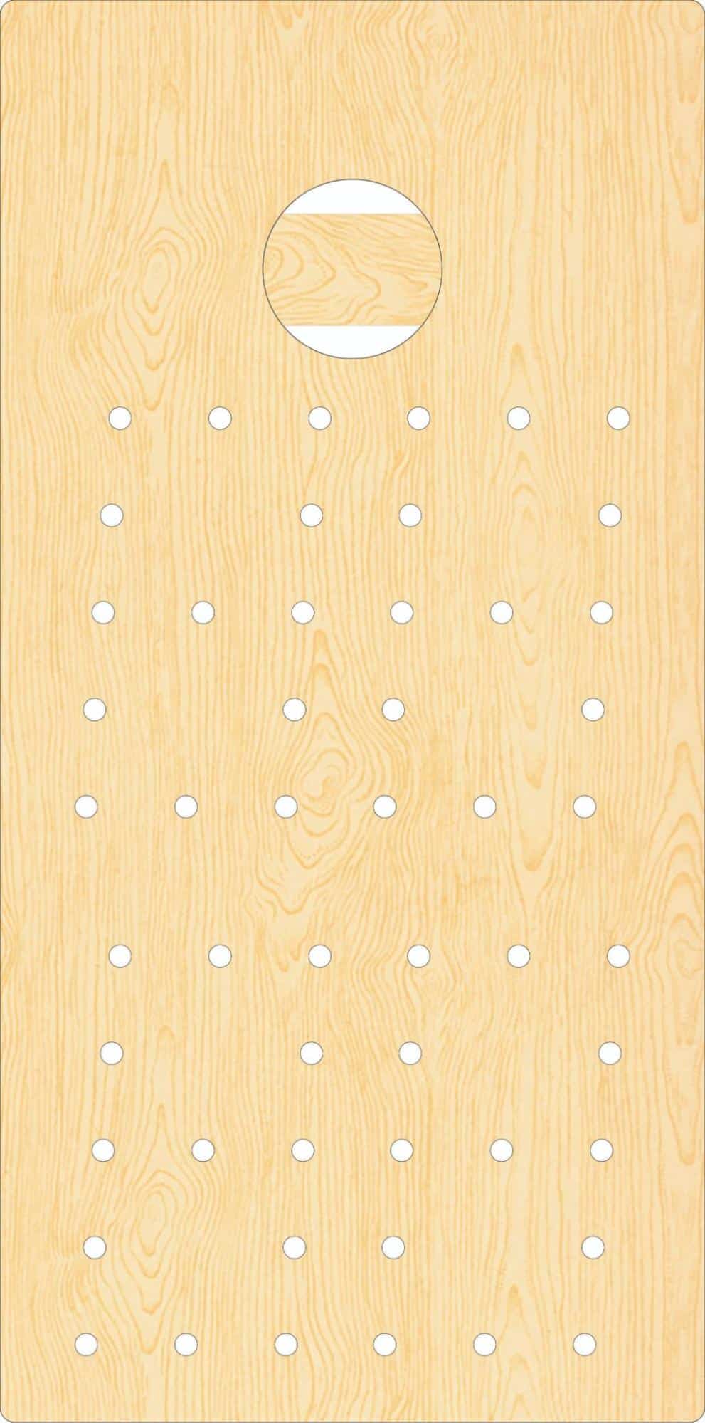
The first step is deciding how the LEDs are going to be laid out. There are an infinite number of configurations that can be used to either optimize playability or to highlight the different design aspects of the boards.
To simplify reading the score when using the tally approach, it's recommended that you keep the LEDs in clusters of 5. There are also various lighting settings that take advantage of the clustered layouts. (see Using The System)
We can also provide LED strands with a large spacing in the middle to help you free up space in the middle of the boards to put clients' logos, etc.
Standard tally kits come with 40 of the larger ¾” LED caps and 64 of the smaller ⅝” caps. The bigger caps are intended to be used for all of the ambient lights, the 5s and the 21s. Other configurations are possible, just let us know what you need.
It is also worth noting that since the LEDs are stranded together, without modifying the strands, there are limitations to how far apart an LED can be from its neighbor. It is recommended that LEDs are spaced no more than 4.5” apart.
It is recommended that the Ambient lights be mounted into each component of the frame (including the center support beam) to light up the surrounding area. This means that neighboring score lights have to stay within reach of the frames. Since the sides of the frames are roughly twice as long as the cross beams, they will each have 2 LEDs. If no support beam is used, plan on installing 3 LEDs into each of the side components.
Alternatively, you can opt for the 7-Segment Display (like a basketball scoreboard). Here's one possible layout.
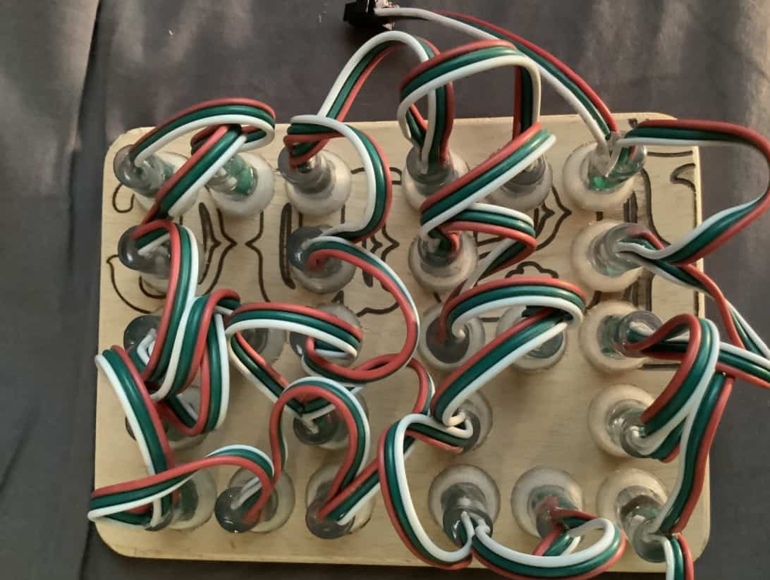
From the back, the LEDs will be installed one at a time, starting from the top right and routed clockwise.
Lastly, ensure that you don't create conflicts between the LED placements and the frame underneath. In other words, don't put LEDs where your frame will be.
After deciding on a layout, it needs to be transferred to the faces and frames of the boards.
The best approach for applying a layout is with a CNC.
CNC machines can be prohibitively expensive. If you don't have a CNC at your disposal, layouts can be transferred to paper with plotter printers and overlaid onto the boards, or the layouts can be transferred directly to the board using a pencil and a carpenter's square. Once the locations of the holes are marked, a power drill, appropriate Forstner bits, patience and skill can produce viable results. A drill press or drill guide is highly recommended to achieve perfectly vertical holes.
*It is recommended that all staining be done and a light coat of poly applied prior to installing the caps.
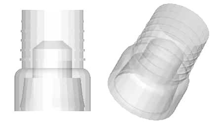
Translucent plastic caps are then mounted into the holes that we've made. The caps come in 2 standard diameters, ⅝” and ¾”. If different sizes are needed, just let us know.
*The caps will inevitably have some resin residue on them. Use latex gloves while handling them.
The caps are manufactured with ribs that help them bite into the holes and hold the glue. It is highly recommended to run some tests with your setup to make sure the hole size is perfect. They should work perfectly with any Forstner bit set, but there's always a chance of manufacturer variation. The goal is to get the caps to sit both flush, and tight with only your fingers. You should be able to remove them, but not too easily. It is recommended that the caps be installed after the design work is complete and a seal coat has been applied. Bear in mind that applying the poly first can make the holes a hair smaller, so you want the caps a little loose prior to Poly.
When actually installing, you'll want the "face" (wherever the lens will be) of the wood up towards you . Put a bead of transparent wood glue around the entirety of the bottom rib of the cap (about ⅔ the way down from the lens). Twist a little as you set them in to help spread the glue out. On the decks, if you're doing clusters of 5, for example, set a piece of scrap wood ( ~7x7" - a little bigger than the cluster) on the caps and tap them all in at the same time with a rubber mallet to get the caps flush with the wood. (Sand or otherwise round over the edges/corners of the block so it doesn't mar the wood) You'll want to wipe off the glue with a wet rag as soon as you can. You won't be able to see the glue after it dries, but definitely don't plan on staining that wood after the glue gets to it.
Get the caps as flush as possible. You may want to use a smaller block (~2x2") or even your thumbs for fine tuning. Every once in a while you may get a stubborn one that takes a little extra cajoling. Take your time on this so that you don't have to apply unnecessary coats of poly to get the surface perfect. If the caps go in too deep, make sure you support the veneer with a block of wood when you pop it back out so that the wood doesn't delaminate or chip.
After the glue dries, test the caps by lightly pressing on them. If any are loose, reinstall them with more glue.
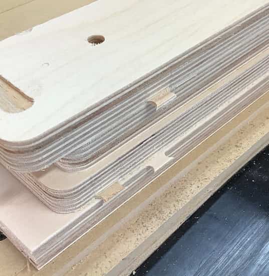
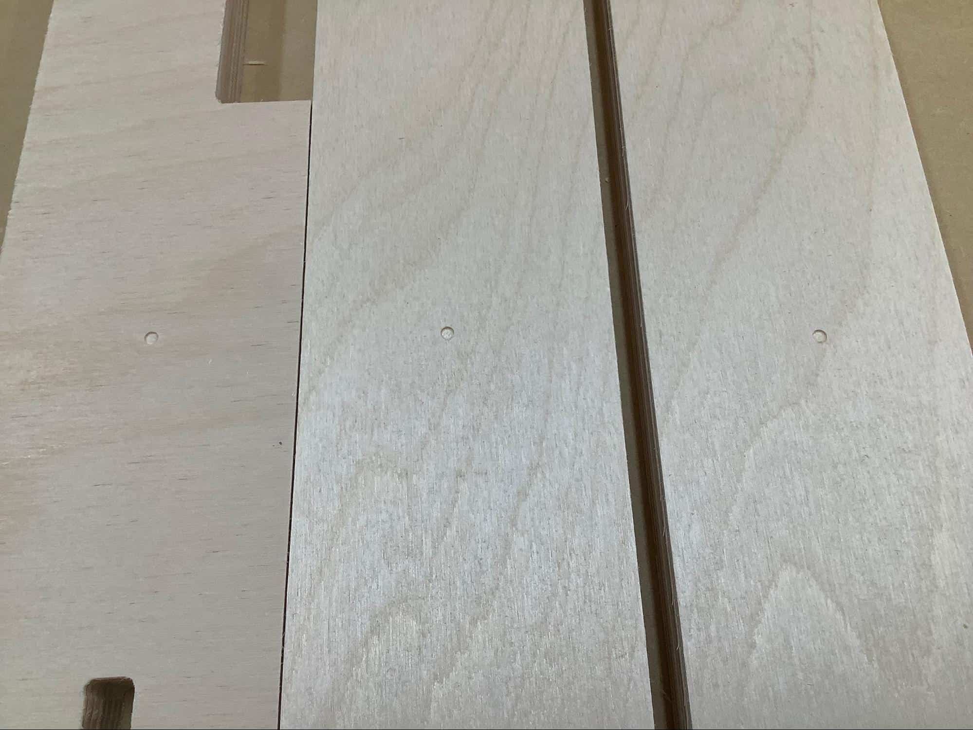
If support beams are desired, it is important to determine not only how the LED strand will be fed through the beams, but also to consider how the beams could interfere with installing the caps and the LEDs into the deck. Simple 3/4” holes will allow the LED strands to pass through the beams without issue.
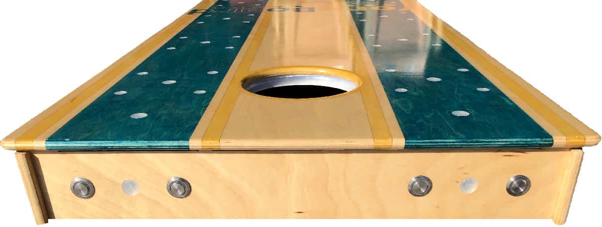
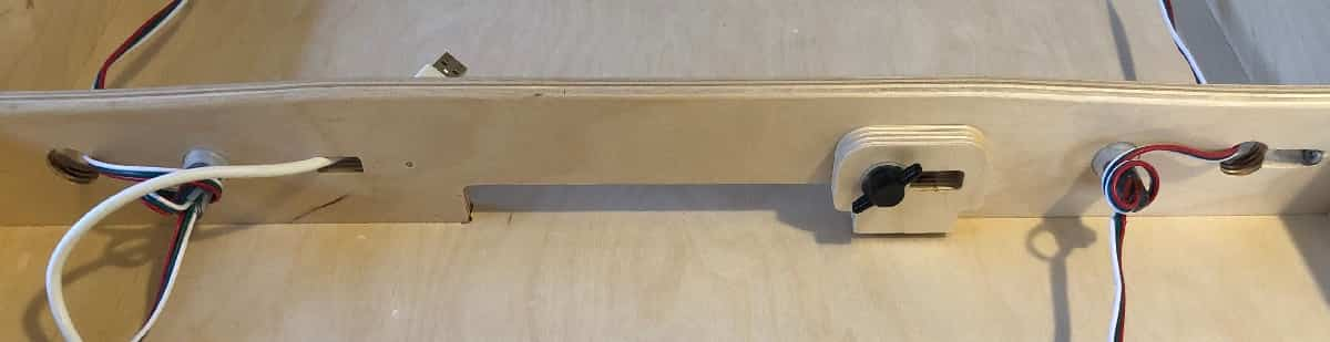
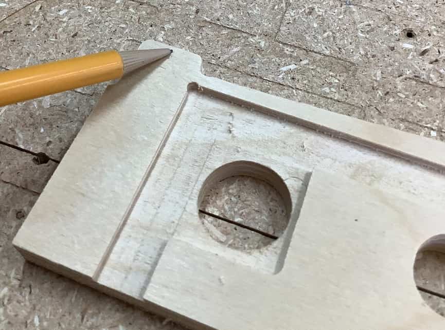
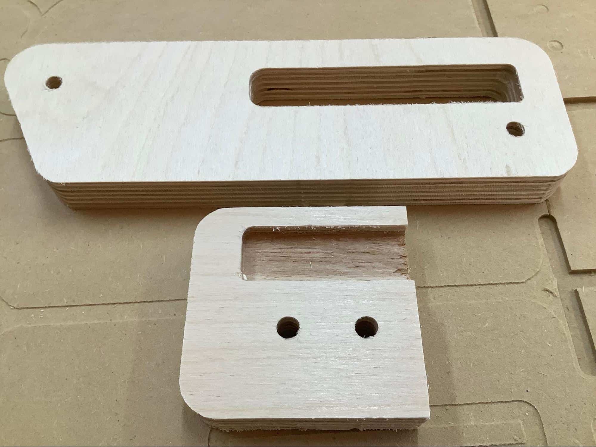
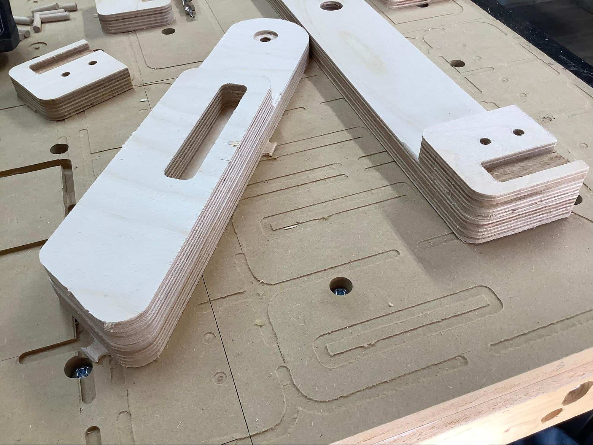
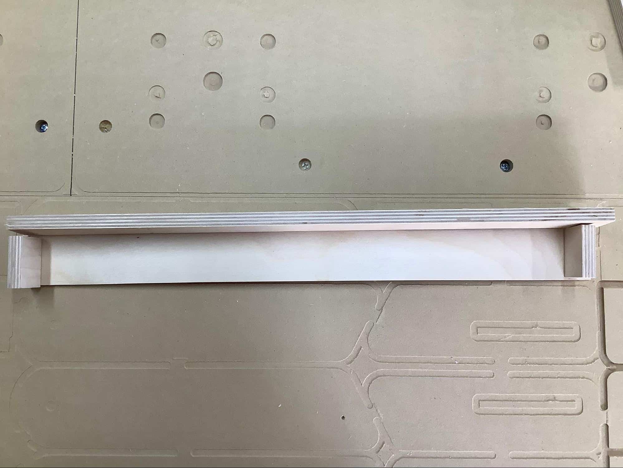
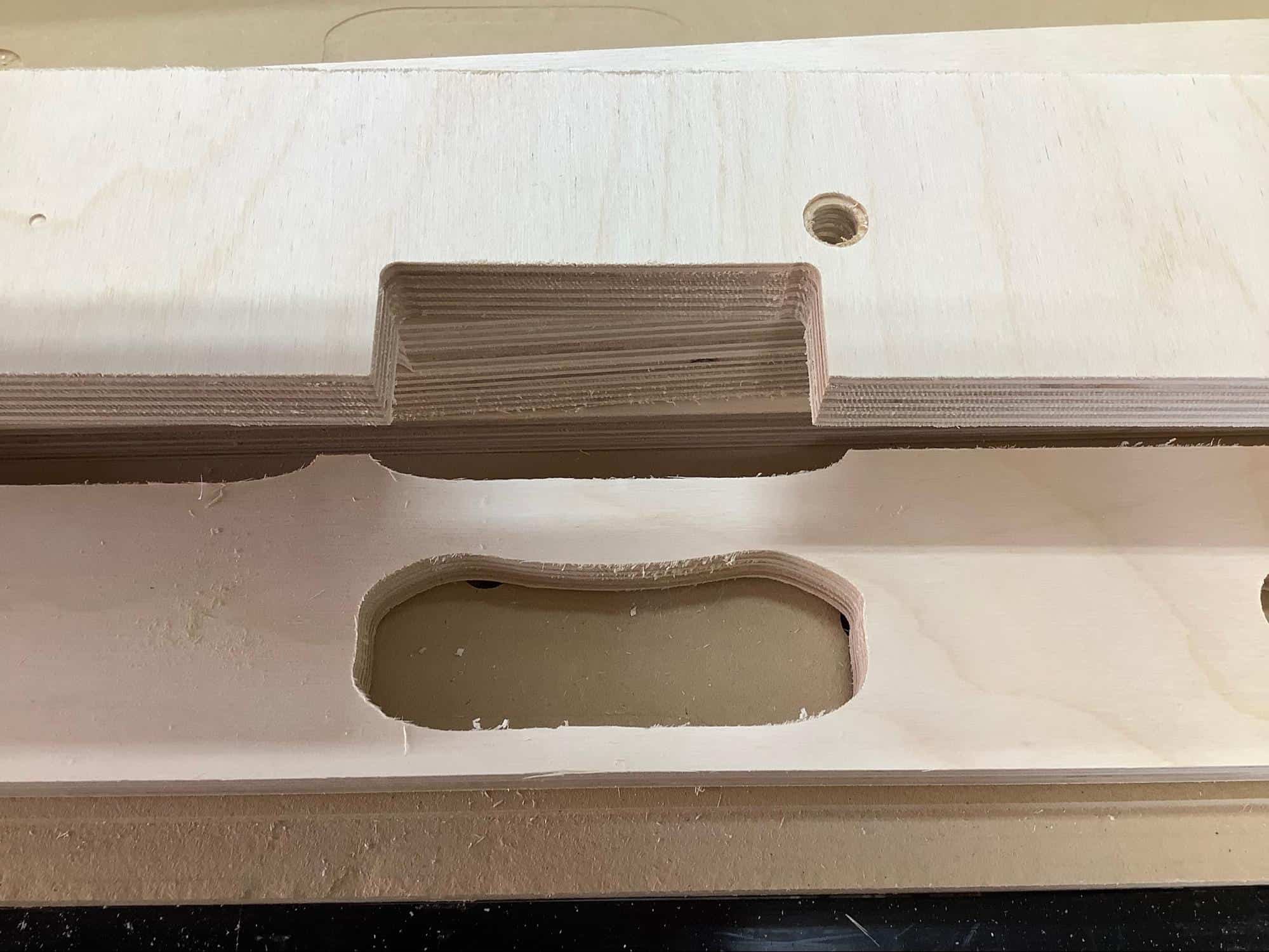
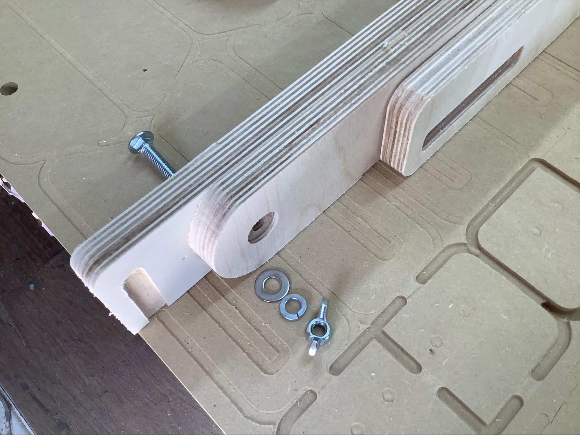
The system is designed to be powered with portable USB chargers. You don't want these powerpacks hanging loose or sitting on the ground. There are many ways to go about this, but creating a slot in the support beam with an adjustable lock is an effective solution (pictured above).
We've tested over 20 different powerpack products and have found that these are the best bang for the buck...
It is recommended that the LEDs (and the rest of the electronics) be installed as one of the last steps. However, the LEDs can be easily snapped in and out of their caps.
To install an LED into its cap, first ensure that you know which LED goes where. It is helpful to power on the system and increase the score as you insert the LEDs into their caps for a sanity check.
Each LED has notches on its sides. The caps are designed with catches that latch onto these notches and secure the LED in place. Simply apply pressure to the LEDs until they snap into place and gently pull straight up on the LED housing to remove them.
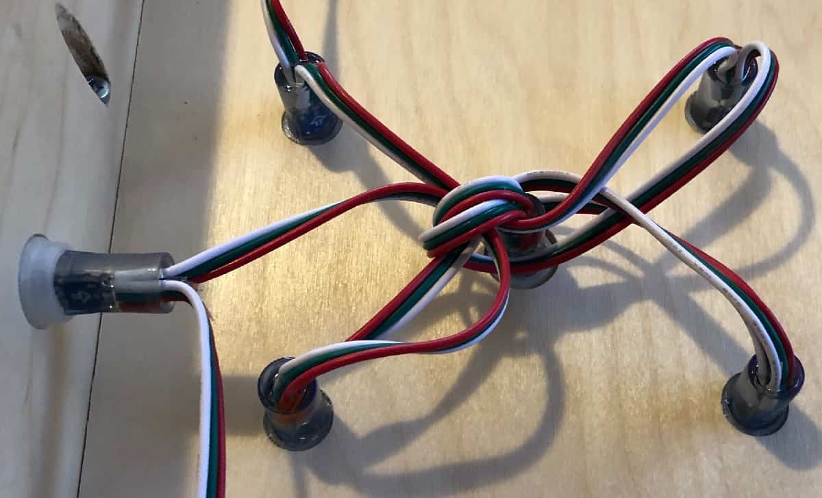
It is also recommended to keep wire management in mind while installing the LEDs. You can use the LEDs themselves to keep the wires tidy.
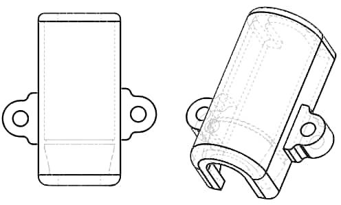
Each strand of LEDs contains five LEDs that are used for ambient lighting. These LEDs are found at the beginning and end of the strand and at equal intervals throughout the LED strands (every sixth LED). It's recommended that these LEDs be mounted into the frame with LED caps, but they can also be mounted to the underside of the face with optional brackets (not included) or something similar. To use these brackets, simply snap an ambient LED into one of them and while being mindful of the direction of the light's projection, position the bracket onto the underside of the board and screw it into place.
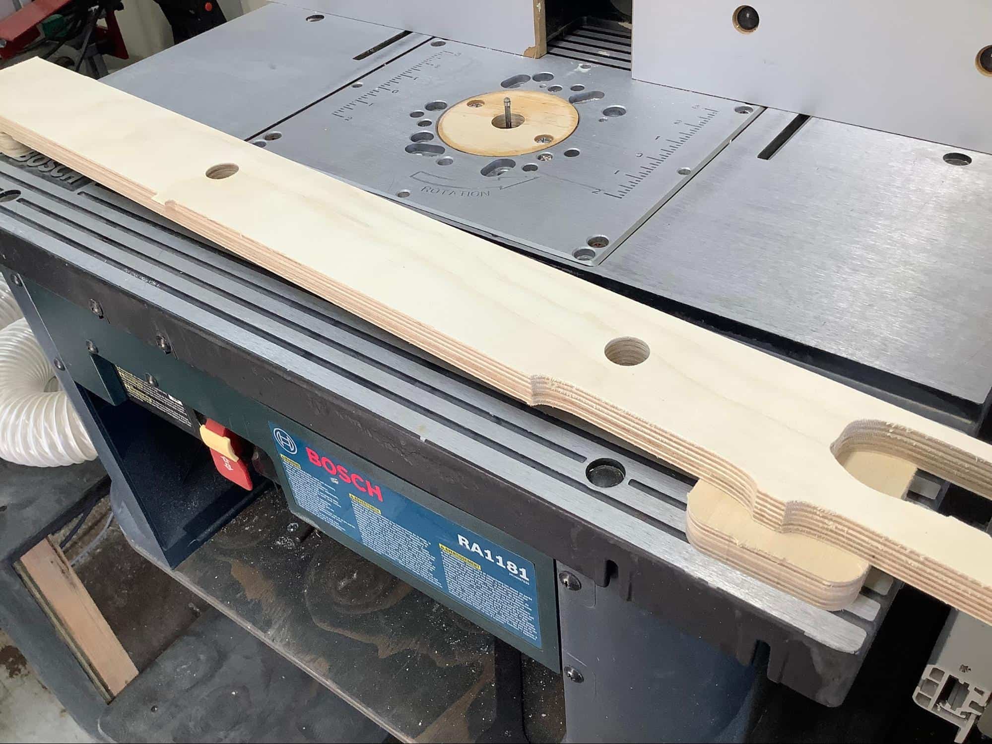
Many of the components will have leftover tabs from the CNC process. Run your flush trim router bit (preferably on a router table) to remove all of these tabs. Many of them will be removed by the roundovers in the next step if you want to identify them and save a little time.
In order to give your boards that smooth touch and sleek look, swap out your flush trim for a roundover bit (with a bearing). We recommend a 3/16” bit, but ⅛” and ¼” should work just fine.
IMPORTANT: You'll want to roundover every edge EXCEPT the following:
- The ¾” sections where the legs rest on the frame while the boards are in use. This one is critical.
- The beef components that will be glued up and rounded over later (see below).
- The edges of the legs and sides that will be doubled up. (There are ½” sections that are already rounded over to mark the edges of these roundovers)
- The underside of the scoring hole (where the ring lights go)
- Any edge that acts as a joinery tongue/tenon
- The components that form the box that protects the electronics
*NOTE: It's recommended that you dry fit all of the components to make sure you understand how everything joins together. It might also be wise to take a pencil and lightly mark the edges that you'll need to round over.
Don't forget to round over the handles on the side rails and the power pack slot too.
In order to maximize stability and surface contact, the 4 corners of contact are designed to be doubled up.
Sand the sections of the sides, legs and beef that will be hard to get to after they've been glued.
For the sides and feet, use the 1” dowels. If the pocket holes were made for you, these dowels will be pre-cut. Apply glue to dowel holes and the faces of both components, join them together, align them the best you can, and clamp (2 clamps each). If youre planning on staining these components, be careful not to use too much glue or it will leak out and prevent uniform staining. Either way, wipe off any excess. Leave them clamped overnight. If the dowels are a little too long, the pocket holes will shave them down.
Follow the same procedure for the legs, but do a dry fit to make sure the dowels aren't too long.
After the glue has set, remove the clamps and run your flush-trim again to make everything…flush. *Part of the leg assembly won't line up, this is by design.
Now you can more safely run your roundover on the beef. So let's do it.
For the sides, we recommend laying down some scrap wood on your router table to rest the piece on.
Pocket holes help ensure everything turns out flat and square, and ensure nothing falls apart.
Each of the following components will get 4 pocket holes.
Sides, Top, Center Support, Bottom, and the Leg Support.
There are indicator marks on most of the components.
*Make sure you drill the pocket holes towards the flat side of the component (not the roundovers)
The sides will have 4 pocket screws going to the deck, one of which will do through the dowels in the beef.
The top and bottom will have 2 going to the deck as well as 2 going to the sides (aligned with the LED holes).
The center support is similar, but we recommend alternating which side you put them on, or just put them on both sides.
The leg supports get 2 on each side going to each leg. Just try to space them evenly.
*Pay attention to which side you put the pocket holes on. You don't want to be able to see them from the outside. It's also highly recommended that you understand the depths of the screws with your pocket hole jig's configuration and that you run some tests first.
Clean up any splinters that might have been created.
Using a Forstner bit (13/16”), make a countersink into the side rails where the carriage bolts (that attach the legs to the frame) will go. A drill press is recommended. It should be as deep as the bore is from the opposite side. Do NOT go deeper. (There should be a small hole indicating where to put the countersinks, if not, drill a small hole through the center of the carriage bolt hole)
The carriage bolts can be tricky to work with after everything is assembled, it's best to seat them now.
Insert a bolt, put on a washer and a butterfly nut. *The lock washer is for final assembly only. Tighten until the top of the bolt is flush with the sides. Remove and set them aside for final assembly.
Nothing in nature is perfect and that especially holds true with plywood. The veneers are normally near flawless, but the inner layers will always have at least a few voids. Take a few minutes to carefully apply wood filler to any of the imperfections. Be mindful not to make a mess though, it can be a pain to sand it off.
Sand everything except the areas that are masked. We recommend 400 grit.
We recommend using gel stains with a heavy dose of patience, but standard oil stains can be used with A LOT of patience.
To stain the masked and lasered areas, first squeegee or brush Poly into all of the laser lines to mitigate bleeding. Use a liberal amount, but make sure there isn't too much excess poly or it can make it tricky to remove the mask.
Use a weeding tool to gently peel up ONLY the sections you plan to stain first.
We recommend doing the dark colors first and sealing in the stain prior to applying the next. Again, if you're too liberal with the poly, you can run into issues. If you don't apply enough, that can cause problems too. Tests are highly recommended.
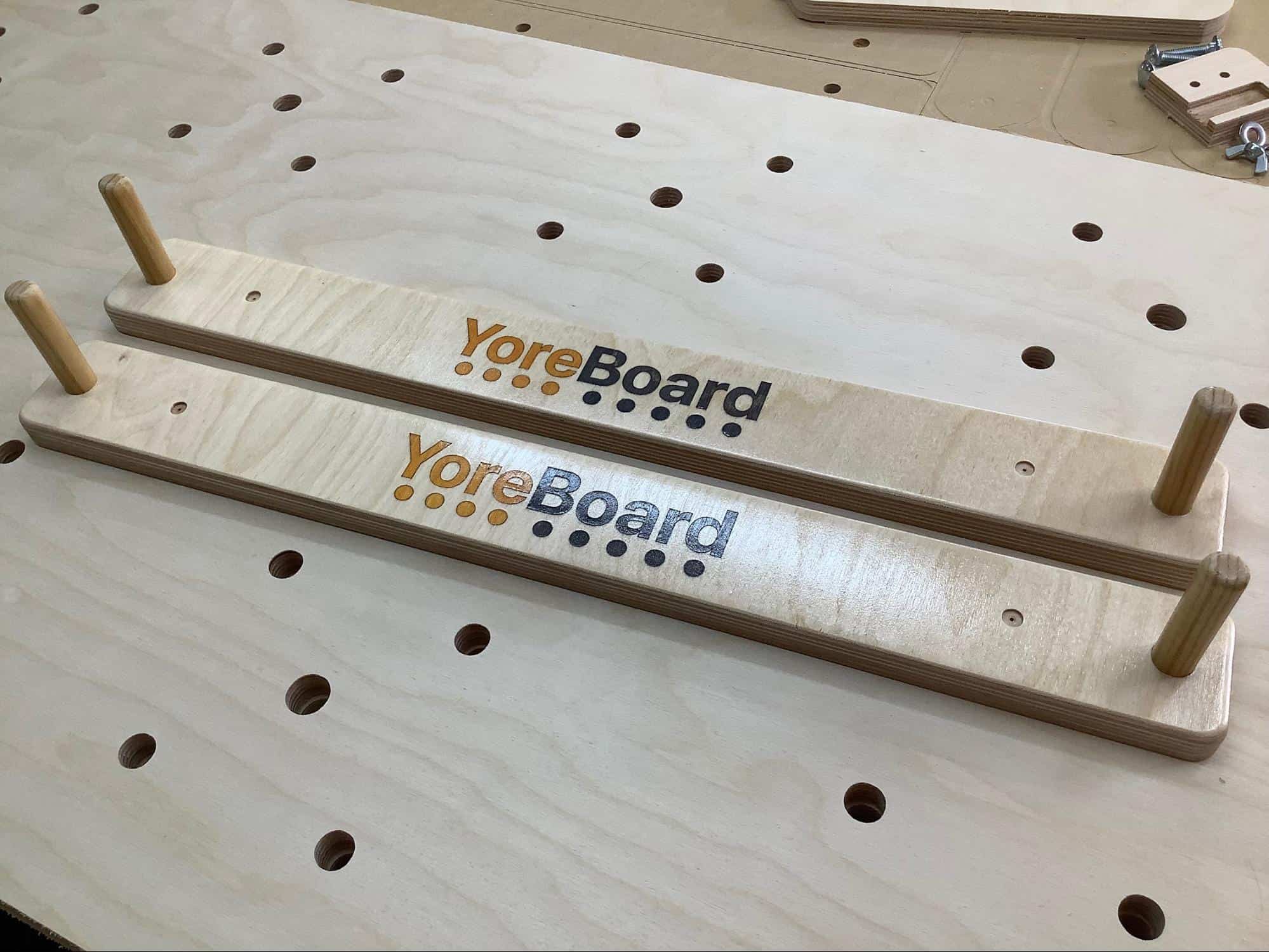
We ask that you stain the “Yore” a lighter color than “Board”, but these are your boards, do as you like.
After staining, you want to peel off the stain at a 45 degree angle from the grain of the wood keeping the peeled mask as low as possible. It's also helpful to gently warm the mask with a heat gun.
Inevitably you'll have some minor splintering, lightly sand them off being mindful of the stained areas.
We recommend:
Lay down a bed sheet on a CLEAN and FLAT surface. Lay the deck (face down) on top of the sheet. We recommend overhanging the electronics side off of the table by about 4 inches for clamping.
Sand the backs of the decks. (400 grit)
Clean out any splinters/fuzzies from all of the grooves.
Gather everything you'll need:
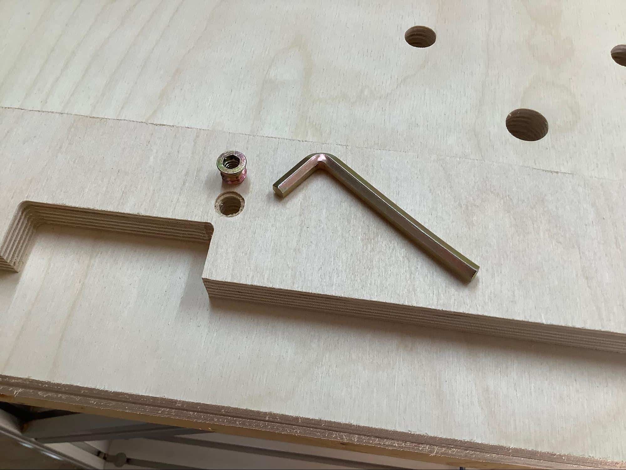
Install Power Lock Insert Nut into center support.
Lay your straight edge across the deck to identify any warps that you need to keep your eye on and lay down weights accordingly to get everything flat. *Leave yourself room to work.
Add glue to the 5 main frame grooves on the deck.
Set in the top, center support and bottom components. The center support should be oriented with the insert nut facing the top of the boards.
Add glue to the 3 grooves of the sides components and set them in.
Clean up excess glue with your small brush, water and rag.
Visually inspect all of your joints and double check everything with your straight edge.
You will have mostly all 1” pocket screws, but there will be 4 1 ½” screws too. Those are ONLY for attaching the bottom to the sides.
Starting with the center support and working your way out, screw all of the components to the deck only.
Again, starting from the center, screw the center components to the side rails. (1.5” screws for bottom)
Clean up excess glue with your small brush, water and rag.
Visually inspect all of your joints and double check everything with your straight edge.
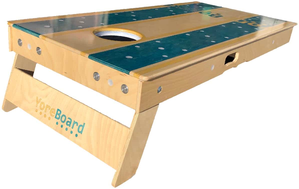
Dry assemble the legs where they will actually be installed. Ensure the logo is facing up and that it is upside down. We want it to be right-side-up when the board is eventually flipped over and set up.
Add glue to the grooves of the legs. Put the legs together and set them into the grooves.
Add all 6 cardboard spacers between the legs and the frames. This ensures there will be room between the legs and frame to allow the legs to open and close.
Center the support the best you can.
Do a dry assembly. *We're NOT gluing on the face of the box.
Carefully run a bead of glue along the grooves on the top of the frame. Insert the small box sides. Add a little glue to the tops of the sides. Insert the top of the box. Using your clamps and blocks, clamp the E-Box into place.
Glue in the power pack stop
Screw on the power pack lock
Let everything sit overnight.
Add the final 4 pocket screws to the leg supports.
Small dents and scratches on the decks are not uncommon during assembly. Plan on doing 1 or 2 final sandings and coats of poly. It is highly recommended that the frame (including the leg support) be protected during the final coat.
Install the electronics (see below)
Install the E-Box face with 5 small screws
The wall mounts are designed to slip into the small gap between the legs and the top of the frame. There are screws at 16” apart for screwing them into wall studs.
Round over the wall mounts prior to assembly. You can stain them first too if you want, but make sure you seal in the stain prior to next steps.
1” screws should be used to secure dowels. Using a Forstner bit, carefully drill countersinks into the back of the wall mount for the screws. If drywall anchors will be used, create countersinks for them too.
Add glue to dowel pockets and insert dowels. Using a square, or something square, ensure the dowels are…square. *Don't install the screws until the glue has cured.
Let glue cure overnight.
After curing, install 1” screws into dowels from the backs of the wall mounts.
2 coats of poly recommended.
The buttons provide players with a straightforward and convenient way to interact with the system. Their main role is in keeping score, but they also provide a means of communicating some preferences. Since there are two scores, there will be two sets of “Up” and “Down” buttons (four buttons total). More details can be found below in the Using The System section.
It is recommended that the buttons be installed into the frame's top component (pictured above). Since the “Up” button is used more than the “Down” button, it is recommended that the “Up” buttons be placed closer to the players than the “Down” buttons. The buttons are mounted into .93” holes and secured with a nut. It is recommended that a pocket be made to house the nuts to ensure that the nut can reach the threads and to make tightening easier.
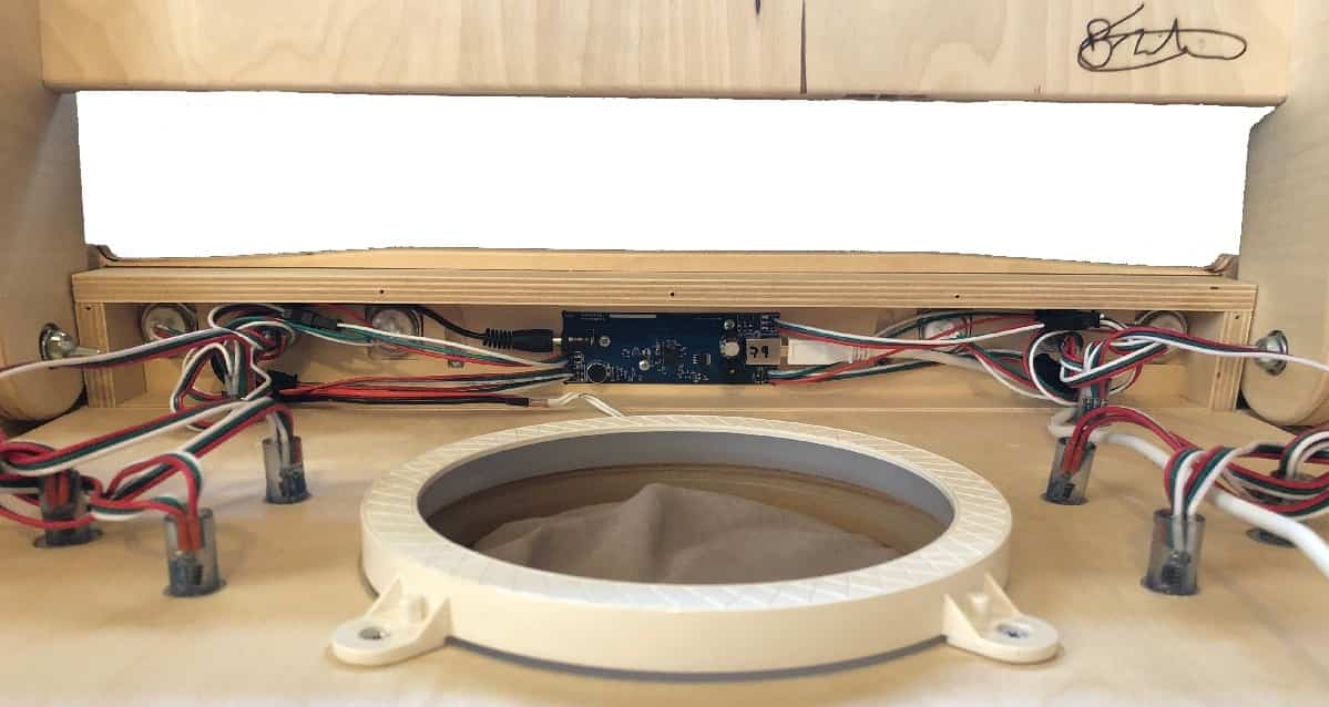
The brain of the operation is the printed circuit board (PCB). It is recommended that it be mounted between the buttons where all of the connecting wires can easily reach. It is necessary for either a pocket to be made to accommodate the PCB and its solder connections, or for plastic washer/risers to be used to keep the solder connections off of the wood. This is both to prevent the board from touching the wood and to prevent the board getting stressed and warped. The head unit is then secured to the wood using screws. Do NOT overtighten. The PCB is roughly 33 x 100mm in dimension.
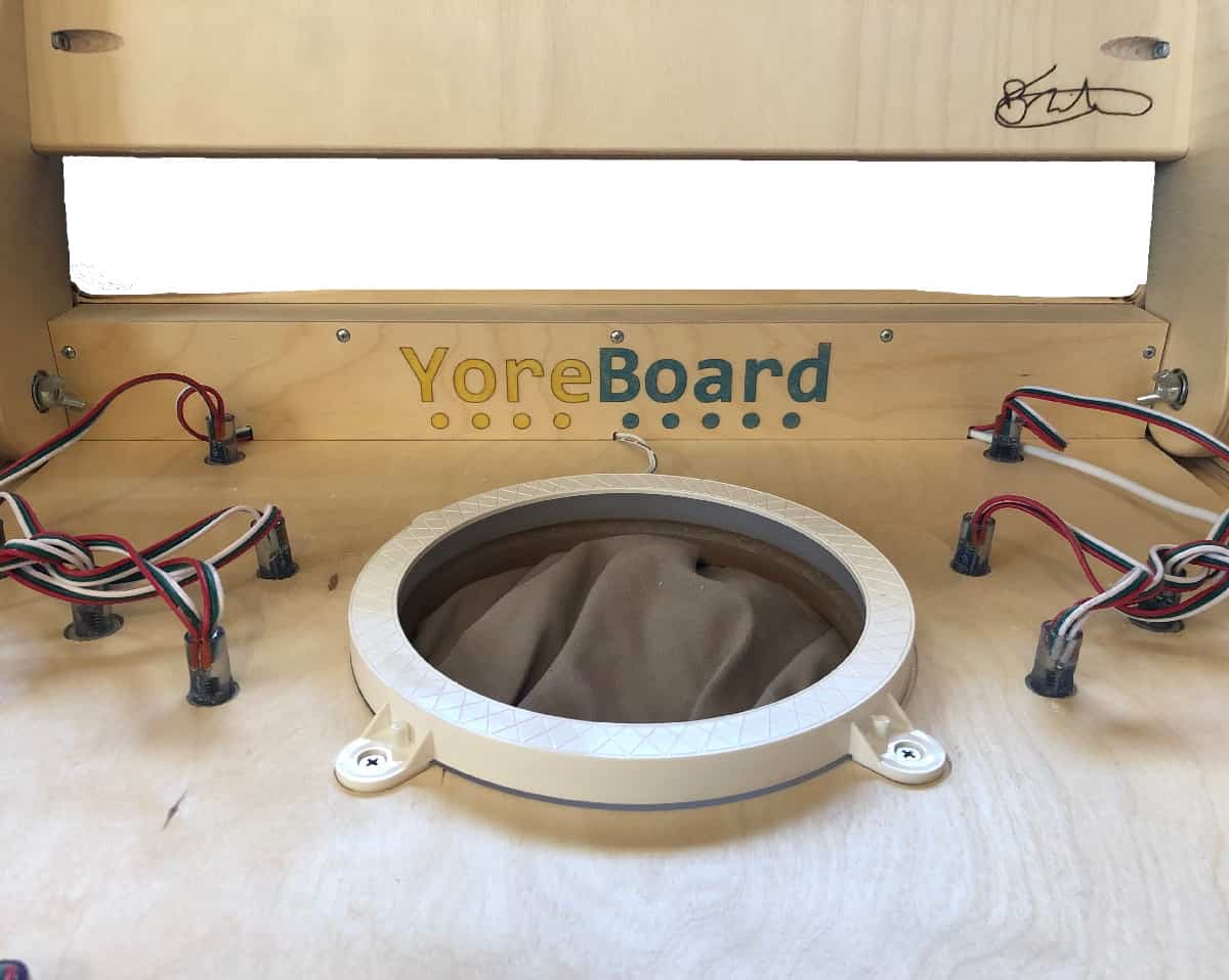
In order to keep everything safe from bags, hands and water sprinklers, a protective housing is recommended. There are many ways to go about this, but creating a wooden box like the one pictured above is perhaps the simplest. Even screwing down an old piece of tupperware is better than nothing. You'll need to put a few notches into the box face to allow the wires in for connecting to the PCB. It's also important that you don't hermetically seal the electronics, they need a little air to dissipate heat.
It's also imperative for you to ensure that the electronics box won't impact the operation of the legs or their carriage bolts.
For further customization, the system was designed to optionally control hole light rings that many already own. More details can be found in the Brightness section of the online help guide.
You should be able to use any rings that you want, but we've tested a number of them and they all worked fine. Recently, due to patent infringement issues, Amazon no longer carries the rings. We have them available if you need some.
The system is designed to accept a male barrel connector that some of these rings are manufactured with. The female connector is not included, but we can attach one for you. If the ring that you're using does not have a male barrel connector, you can easily solder the wires directly onto the circuit board. (You can find the necessary male connector on the internet or we can provide them too)
Strip the wires and test the LEDs to ensure you know which wire is ground. The black wire of the male barrel connector goes to the ground wire of the ring.
Make sure you protect any solder joints with heat shrink tubing that could potentially cause shorts.
Please refer to the online help guide for a crash course in using the scoreboard.
Don't hesitate to reach out if you have any questions or suggestions. We genuinely want you to succeed and to be as happy with our products as possible.
We'd also love to see the finished product. Please shoot us some pictures if you're up for it. And obviously, we'd really appreciate you sharing with your friends and family on social media, or leaving us a review in Google or in the app stores.
Thank you for your support. Enjoy!